Itty Bitty Radio Telescope Data Logging Modifications
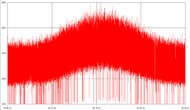
I decided to work on the logging issue with my telescope, as the graph of data produced last time was very noisy. As I couldn't take the meter input directly into the microphone input of the computer, I decided to add a power jack to the satellite finder so that the buzzer could still work while I had the unit connected to my computer.
I purchased a splitter so that the LNB could feed both the finder and my computer connected through an SDR (Software Defined Radio).
I had to modify my finder because I wanted to be able to plug DC power into it from a jack instead of the connector on it. To open the case, I had to remove the dB knob from the front.
I didn't always want the buzzer running while taking measurements. The sound is very irritating to listen to for a long period of time, but it is very useful when trying to aim the telescope. So I wanted to install a switch to be able to turn off and on the buzzer.
The next step was to add the appropriate connector to the DC power source so I can connect it to the satellite finder.
Now that the modifications have been completed, the telescope is ready to take measurements again.
I purchased a splitter so that the LNB could feed both the finder and my computer connected through an SDR (Software Defined Radio).
 |
| Splitter |
The splitter I purchased had to have the DC power pass between the input and only one of the outputs. This is important because I didn't want the DC power needed to run the finder and the LNB to enter the SDR. It isn't designed to take the DC power in.
 |
| SDR |
 |
| SDR connected to splitter |
 |
| Everything connected to the computer |
 |
| Splitter installed with SDR feeding to computer |
 |
| Preparing finder for modification |
 |
| Insides of the satellite finder |
 |
| I removed the PCB from the finder |
 |
| PCB removed |
 |
| Adding wires to allow switching of the buzzer |
 |
| Close up of wires |
 |
| Adding more wires |
 |
| Adding wires for DC power |
 |
| Hole in case |
 |
| Everything soldered together |
 |
| Everything in place in the case. Switch installed in the hole. |
 |
| Back cover snapped back into place |
 |
| All finished with switch and DC power jack installed |
 |
| Adding connector to DC power source |
 |
| Soldering work |
 |
| Finishing up |
 |
| All done |
Comments
Post a Comment